Virtual Firewall and Networking – Planning Guide

This is a planning guide on how to create a robust, redundant, virtual network for your home-lab environment including a virtual firewall. This requires a lot of existing hardware and expertise. This is not recommended the faint of heart and will challenge you. Using a physical firewall is the easy choice.

Cisco_Nexus_3000_Series_1

I have structured this guide around how I have my own network configured for the vSkilled home lab. I have been running in this configuration for literally years without incident. You should first weigh the pros and cons for your own environment and then decide if this design is the right choice for YOU. Just because it works for me, does not mean it will work for you. There are many mixed opinions between running your firewall physically or virtually. Neither is right or wrong. That really depends entirely on your skill level and the equipment you have available. You should decide on a network topology which you are most comfortable troubleshooting and fixing when it breaks.

Continue reading…

Firewalls for Home Use

A question I see often is what firewall is the best for a home/residential environment? Before I get into that, we must realize that the majority of non tech-savvy people do not even have a firewall, or they have one but it’s not enabled/configured correctly, or they’re just not sure. In an age where we see more weaponized vulnerabilities and threats year after year – this is a huge problem. The problem though, is as big as an issue for consumers as it is for businesses such as ISPs and network device manufactures.

Home router firmware hasn’t change much over time. In early 2016, The Wall Street Journal looked at the security capabilities of the top 20 home routers. Only six of those had up-to-date firmware at that time, and just two of them had good password processes. The recent ASUS settlement with the Federal Trade Commision over the critical security flaws in their home routers is further proof that home router manufacturers don’t take security seriously. Today’s home router selections don’t offer you the flexibility to set up your network the way you see fit. They also don’t provide you visibility into the devices that are connecting to your network says Untangle.

There is a wide array of security practices that would probably make you shake your head.  Just the other day I was at my parents place and found that the ISP provided modem/gateway’s firewall was set to “NAT only”. The firewall was disabled and it even stated that this was the default option and that enabling the firewall was “optional”. I would highly suspect that this is the default configuration for all of the ISP’s customers. This means the firewall functionality and security legwork is responsibility of the end-device. Scary! Continue reading…

Home Labs: Remote Access and Security

I am sure that most who have a lab environment in their home also have a way of remotely accessing it – either from at work, with friends or family, vacation, etc. The problem with any remote access into a secure network is that you are quite literally punching a hole into your network from a security sense to allow that to happen.

People seem to have a lot of mixed feelings about allowing Remote Desktop Protocol (RDP) into their home network from the Internet. As a general blanket statement without context, I would completely agree. Opening RDP (port 3389) directly to the Internet without any other security measures in place is asking for trouble. The default RDP port will be constantly brute forced, port scanned, exploited, and the list goes on.

With that said there are steps you can take to have secure remote access to your home network using RDP, SSH, etc.

Many of these concerns can be minimized or eliminated using some of these best practices:

  1. Restrict access using firewalls
  2. Change the listening port for Remote Desktop Protocol
  3. Use two-factor authentication
  4. Use strong passwords
  5. Set an account lockout policy

1 – Restrict access using firewalls

Having a proper firewall and firewall rules in place is critical for protecting your network from outside threats. And I’m not talking about the built-in firewall on your ISP’s provided/rented crappy router/modem – these are a very poor excuse and implementation of a “firewall”- not to mention your ISP normally hard codes back-doors and default logins. I’m talking about a real firewall either physical or virtual, for example; Cisco ASA, Cisco Meraki, Untangle, PF Sense, Sophos UTM/XGUbiquiti, etc. Any of these will give you the tools required to properly firewall your home network. All of these firewalls will require a ‘geek’ to properly setup – keep in mind this article is targeted to home lab hobbyists.

basic_network
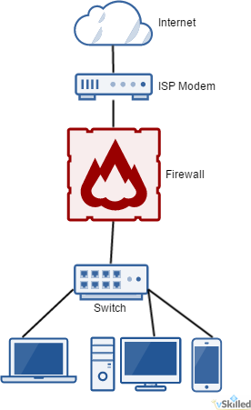
To the right is a good example of a very basic home network with a firewall. Anything before the firewall we treat as untrusted. The firewall is literally the barrier between your network and the big, bad, Internet. There you will define your firewall rules to allow remote access and other functionality (or lack-thereof).

Personally, I use Sophos UTM (see my homelab) with a DNAT (Destination Network Address Translation) rule to redirect the external facing remote access port to a specific server and port on my internal network. This allows me to create a matching condition (For traffic from, Using service/port, Going to) to apply an action (Change the destination to, And the service to) to define what happens when something wants to connect to my network. Using that logic I can (and do) restrict the IP blocks allowed to connect to my remote access port, what times of day, etc.

This allows me to both A; define a custom externally facing port without having to change the port on the server internally, and B; create firewall rules to restrict access even further from specific traffic sources, destinations and services.

The real-world implementation of this will vary based on your choice of firewall, your skills and personal preferences.

2 – Change the listening port for Remote Desktop Protocol

Changing the listening port of RDP is a quick and easy method of implementing security through obscurity. Doing so will help to hide your RDP port from threats who scan networks looking for computers listening on the default Remote Desktop port (TCP 3389).

There are a number of ways to accomplish this. 1 – port redirection on your firewall/router, 2 – modifying the registry keys of the Windows computer locally, or 3 – using a Windows TS Gateway. Choose the method that works best for you.

3 – Use two-factor authentication

Using 2FA (two-factor authentication) is a no brainier these days. Two-factor authentication provides a second layer of security to any type of login, requiring extra information or a physical device to log in, in addition to your password. This protects user logins from remote attacks that may exploit stolen credentials.DuoScreen_740
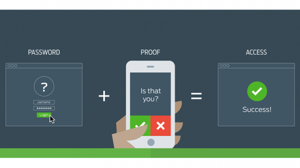
I use Duo Security Personal edition on my remote RDP access to my home environment. I have configured Duo to only prompt 2FA if the source IP is external. That way I don’t need to use 2FA for local RDP sessions from within my LAN – which would just be annoying. Any time I want to login I just connect, enter my credentials, answer the 2FA prompt on my phone, and I’m in. The Duo Dashboard also has a wide range options, logging, and device fingerprinting. Duo works on a huge number of operating systems and platforms so you can integrate it into, almost, literally any part of your network as you deem fit.

If you are not already using 2FA in your network, start using it! It’s free and extremely easy to setup.

4 – Use strong passwords

While this one may seem like common sense, you would be surprised. A strong password should be at least 8 characters long using a combination of upper and lower case characters – including a mix of both numbers and symbols. Setting an insecure password on anything, let alone a remote entry point to your network could spell disaster.

One of the best ways to ensure that you use unique and strong passwords for systems and websites is to use a password manager. I personally use and recommend Dashlane.

5 – Set an account lockout policy

Brute force attacks are common problem for external facing ports and services. Remember that two-factor authentication only comes into effect once the password is correctly entered and will not prevent a brute force attack. Setting your computer to lock an account for a period of time after a number of incorrect guesses will help prevent attackers from using automated password guessing tools to break into your account.

  • Go to Start–> Programs –>Administrative Tools–> Local Security Policy
  • Under Account Policies –>Account Lockout Policies, set values for all three options.
    • 3 invalid attempts with 3 minute lockout durations are reasonable choices.

Conclusion

Hopefully these tips can help you to increase the security of your home network and remote access methods. If you know what you are doing and if done correctly you can have secure remote entry into your home network. This is not meant to be a be-all-end-all guide as there is no one size fits all for network security. This guide doesn’t even begin to dive into the more complex aspects of network security such as advanced threat protection, intrusion prevention, spoof & protocol protection, and so on.

Have more home lab security tips to share? Post them in the comments below!

Migration from Cisco 1000v to VMware Virtual Distributed Switch (Part 1)

Cisco_Nexus_3000_Series_1
While working with a enterprise customer I was tasked with migrating an entire production environment from the Cisco Nexus 1000v to a VMware Virtual Distributed Switch (VDS). Then moving the VDS and the ESXi 5.1 hosts over to a fresh built vSphere 6.0 server. The customer is in the middle of an upgrade from vCenter 5.1 to 6.0. Most of the host upgrades will be done once the hosts are moved over to to the new vCenter.

Goals:

  • Non-disruptive migration of networking for Virtual Machines (this is a live production environment)
  • Migrate away from the Cisco 1000v, to VDS
  • Migrate the VDS config from old 5.1 vCenter to new 6.0 vCenter
  • Touch-up naming of virtual machine networks/VLANs
  • Move Virtual Machines from the Virtual Distributed Switch (VDS)/Nexus 1000v to a Virtual Standard Switch (VSS)
  • Disconnect and remove the ESXi hosts from the old vCenter 5.1
  • Connect ESXi hosts to the new vCenter 6.0
  • Migrate VM networking from VSS to VDS

VMware vSphere 5.1 and later allow you to export, import, or restore Distributed Switch configurations from the vSphere Web Client. Since moving the 1000v would be too convoluted, if not actually impossible, I will move everything over to a VDS on the existing 5.1 vCenter first. Then once everything is up and running on the VDS we can then migrate the VDS configuration over to the new 6.0 vCenter server.

000193_2015-10-29 10_06

Unfortunately we will also need to create a Virtual Standard Switch (VSS) switch configured with all the networks, all with matching configuration on each ESXi host in order to actually do the ESXi host migrations over to the new 6.0 vCenter. This will be automated with scripts, of course. We must migrate all virtual machine, VMkernel, and service console networking from VDS to VSS so that network connectivity is not lost when we remove the hosts from the VDS in order to disconnect them from the 5.1 vCenter and add them to the 6.0 vCenter.

MIGRATION FROM 1000v to VDS

Summary:
The following steps will migrate the host and VM networking from the Cisco Nexus 1000v to a VMware Virtual Distributed Switch. This migration plan assumes that there are at least two dedicated uplinks for VM traffic. The purpose of this is to remove dependencies on the legacy 1000v and create a known working configuration of the VDS that will later migrated to the new vCenter 6.0 server. The customer has decided against using the 1000v and wants it removed from their environments. We need to perform this migration before we can move the hosts to the v6.0 vCenter so that we have a working VDS configuration that we can later export to the new vCenter and as a result have an immediately working VDS configuration.

I performed the migration in two parts; that I named “legs” which is basically a reference to the actual uplinks (A + B) themselves. This is to ensure I can quickly and easily roll-back the change if necessary. For the duration of the migration we will only be on one “leg” at a time (either the 1000v on uplink A – or – the VDS on uplink B), this of course introduces a single point of failure but the risk is acceptable since the change window is quite small and the chances of a switch or uplink failure during our change is low. Regardless, I will ensure that both the 1000v and VDS are fully working at all times until all VM networking is migrated from the 1000v to the VDS – testing along the way to ensure there is no impact to VM networking. Once all VMs are moved from the 1000v then we can remove the uplink to the 1000V which at that point should be completely unused and add that uplink to the VDS so that we can then achieve our A+B uplink redundancy again.

Pre Tasks:

  • *** Disable HA, DRS, and EVC on the Cluster ***
  • *** Storage DRS needs to be set to manual or disabled ***

LEG 1
The following will put the hosts into a split 1000v + VDS configuration. One leg on the 1000v, one leg on the VDS. This is necessary to allow proper configuration verification and full migration of VM networking. During this time however, VMs will only have 1 uplink on either side which introduces a single point of failure. However this will only be for the duration of the migration and then they will move back to 2+ uplink paths.

1 – Place target host into maintenance mode
2 – Remove ONE host uplink to the 1000v
3 – Attach host to new VDS using the now available vmnic that used to be on the 1000v
4 – Remove host from maintenance mode
5 – Use Testing VM to verify networking is working (at your discretion)
6 – Repeat process for all hosts individually

LEG 2
The following will migrate the 2nd leg into the uplink group of the first to allow proper link redundancy on the VDS. Currently VM networking should be working on both the 1000v and VDS. The following steps will fully disconnect the 1000v and migrate VM networking to the VDS. This will allow the removal of the 1000v while the VMs continue running without interruption.

1 – Using the ‘Migrate Virtual Machine Networking’ tool migrate ALL VM networks as required from the 1000v to the VDS networks
2 – Repeat the Migrate Virtual Machine Network for each VM Port Group until all VMs are migrated
3 – ** At this point all VMs should be running from a VDS **
4 – Place target host into maintenance mode
5 – Remove host from the 1000v
6 – Add the vmnic that was on the 1000v to the VDS uplinks
7 – Packet Control (etc) vmnics should show as DOWN on the host
8 – Remove host from maintenance mode
9 – Repeat process for all remaining hosts

Post Tasks:
– Re-enable HA, DRS, EVC, and Storage DRS as appropriate
– Export working VDS configuration to the new v6.0 vCenter server

We’re done!

This migration was completed successfully for the customer in all development, staging, and production VMware environments. During the migration we even took the time to clean-up and standardize the network names of the VM port groups consistently across the environments. I hope this guide can be helpful if you find yourself in a similar situation.

Click here for Part 2, where we will migration the VDS to VSS networking so that we can move the hosts to the new vCenter server, the move back to the VDS on the new vCenter 6.0!

If you have any comments, questions, or suggestions please let me know in the comments section below!


References / Sources:

ARIN Region IPv4 Free Pool Reaches Zero

v4_v6_table

Well it has finally happened. The IPv4 free pool for the ARIN region is now fully depleted. ISPs are encouraged to utilize IPv6 for additional customer growth and the IPv4 transfer market for their IPv4 interim needs.

A copy of the announcement:

From: ARIN <[email protected]<mailto:[email protected]>>
Subject: [arin-announce] ARIN IPv4 Free Pool Reaches Zero
Date: September 24, 2015 at 12:04:22 PM EDT
To: <[email protected]<mailto:[email protected]>>

On 24 September 2015, ARIN issued the final IPv4 addresses in its free
pool. ARIN will continue to process and approve requests for IPv4
address blocks.  Those approved requests may be fulfilled via the Wait
List for Unmet IPv4 Requests, or through the IPv4 Transfer Market.

For information on the Waiting List, visit:
https://www.arin.net/resources/request/waiting_list.html

For information on IPv4 Transfers, visit:
https://www.arin.net/resources/transfers/index.html

Exhaustion of the ARIN Free Pool does trigger changes in ARIN’s
Specified Transfer policy (NRPM 8.3) and Inter-RIR Transfer policy (NRPM
8.4). In both cases, these changes impact organizations that have been
the source entity in a specified transfer within the last twelve months:

“The source entity (-ies within the ARIN Region (8.4)) will be
ineligible to receive any further IPv4 address allocations or
assignments from ARIN for a period of 12 months after a transfer
approval, or until the exhaustion of ARIN’s IPv4 space, whichever occurs
first.”

Effective today, because exhaustion of the ARIN IPv4 free pool has
occurred for the first time, there is no longer a restriction on how
often organizations may request transfers to specified recipients.

In the future, any IPv4 address space that ARIN receives from IANA, or
recovers from revocations or returns from organizations, will be used to
satisfy approved requests on the Waiting List for Unmet Requests. If we
are able to fully satisfy all of the requests on the waiting list, any
remaining IPv4 addresses would be placed into the ARIN free pool of IPv4
addresses to satisfy future requests.

ARIN encourages customers with questions about IPv4 availability to
contact [email protected] or the Registration Services Help Desk at
+1.703.227.0660.

Regards,

John Curran
President and CEO
American Registry for Internet Numbers (ARIN)


This means a number of things for the Internet as we know it. The costs of IPv4 IP addresses will increase significantly. This will hopefully help force the push to to IPv6 in the future since it would be more cost effective and generally the ‘right’ thing to do.

Some major providers on the other hand are alarmingly still very far behind in their IPv6 adoption than they probably should be considering this important announcement. Many parts of the internet are IPv6 enabled and ready to be used. The whole reason for the inertia against going to IPv6 is “if it ain’t broke, don’t fix it”. Well now it is broken.


Windows Server 2012 R2 – DHCP High Availability / Fail-over Setup Guide (Part 2)

windows_server_2012

Part 2 – Setup of Windows 2012 R2 DHCP Failover

Click here to go to Part 1

This build will required 2 x Windows 2012 R2 servers. They both must have the DHCP role installed in preparation for the DHCP fail over configuration. I will not cover the installation of the the OS in this guide.

In this guide I simply used two VMware virtual machines in my home lab to accomplish this. The two servers I used are actually my domain controllers as well. In a production environment it would be best to have this as a dedicated role on the servers, depending on the size & requirements of the environment. We will be building a DHCP Hot-Standby cluster.

1 – Server Preparation

  1. Build your two required Win. 2012 R2 servers.  Your servers should configured with an IP address, DNS, domain, etc and should be fully functioning on your network.
  2. Ensure that the DHCP role is installed on both servers. From the Server Manager select the Manage button, and click Add Roles and Features.
    000145_2015-07-06 13_40
  3. Select “Role-based or feature-based installation“. Click Next.
  4. Select your server from the list in the pool. It should reflect your FQDN and IP appropriately, ensure this is correct. Click Next.
  5. From the Roles list, select “DHCP Server“. Another prompt will appear to install the management tools. Click Add Features, then click Next.
  6. Skip to the end of the installer and click Install. The DHCP role will be installed. Repeat this process on the 2nd server.
  7. Open the DHCP management utility from the Administrative Tools folder on your primary server. This gives us a view of the DHCP installation on the local server. From the DHCP root menu, right click and select “Add Server” as shown.
    000146_2015-07-06 13_54
  8. Enter the FQDN or IP of your 2nd Win. 2012R2 server and click OK. This will add the second server into the view so that we can manage both servers from here.

2 – Scope Setup

Before we can setup DHCP failover we need at least one DHCP scope configured. This scope should ONLY be configured on the primary DHCP server and MUST NOT be added to the secondary DHCP server.

  1. On your primary server only – Right click on the IPv4 object. Click “New Scope…”. This will add a new IPv4 scope.
  2. Enter the Name and Description of your DHCP scope. Click Next.
    000147_2015-07-06 14_01
  3. Enter the IP range of the scope as well as the subnet length and mask. The mask should be generated for you based on the length you enter. A /24 would include 254 usable IP’s which is more than sufficient for this test.
    000148_2015-07-06 14_08
  4. You will be promoted for any exclusions or delays. Add if required. Otherwise click next.
  5. Enter the lease duration for the scope. I will leave this at the default of 8 days. Click Next.
  6. Select “Yes, I want to configure these options now“. This will allow us to configure the gateway, DNS servers appropriately so that clients who get an IP address can communicate properly on our network.
  7. On the Router / default gateway page enter the IP address of your router or aggregate switch here. Click Add, then Next.
  8. On the DNS Name and DNS servers page enter the domain of your environment and the DNS servers that you want clients to use. Click Next.
  9. Add a WINS server if you have or need one. (Probably not.) Click Next.
  10. Finally you will be asked to activate the scope now. Select “No, I will activate the scope later“, or you can enable it if you wish. Click Next, then click Finish.

3 – Failover Cluster Configuration / Setup

Now we will configure the DHCP failover cluster on the DHCP scope(s).

  1. Right click on the root IPv4 menu and click “Configure Failover…”.
  2. By default “Select all” is selected. If that is okay, you can leave that selected. Otherwise you can manually select the IPv4 scope(s) that you want to have failover enabled on. Click Next.
    000149_2015-07-06 14_22
  3. Enter the FQDN or IP of the secondary DHCP server and click Add Server. Click Next.
  4.  Configure the Failover Relationship options. (Please see below for an explanation of these options!)
    • Relationship Name: <enter a name for your DHCP failover relationship>
    • Max Client Lead Time: 1 hour (default)
    • Mode: Hot-Standby
    • Reserve Addresses %: 5% (default)
    • State Switchover Interval: Checked, 1 hour
    • Enable Message Authentication: Yes
    • Shared Secret: <configure a secure password>
      000150_2015-07-06 14_43
  5. Once you have configured the options to your liking, click Next. A summary screen will appear. Click Finish to create the failover relationship.
    000151_2015-07-06 14_48
  6. You will get a screen that shows the status of the replication of your scope to the partner/secondary server. Ensure everything shows as “successful” and close the window.
  7. We have now successfully setup a Windows 2012 R2 DHCP  hot-standby fail-over cluster!

Going Deep – Explanation of Windows 2012 DHCP fail-over configuration options

In summary, the State Switchover Interval needs to be configured so that the servers will automatically failover to the standby server without manual administrator intervention. We must also configure the MCTL value so that the partner server can issue temporary leases addresses until the standby server takes full control of the scopes which happens after the State Switchover Time expires and the partner transitions to Partner Down state.

Both DHCP servers in a failover relationship must maintain a persistent TCP connection with each other. DHCP failover partners establish and maintain this connection on port 647, and use it to exchange operational state information and lease information.

State Switchover Interval: If automatic state transition is enabled, a DHCP server in communication interrupted state will automatically transition to partner down state after a defined period of time. This period of time is defined by the state switchover interval. A server that loses communication with a partner server transitions into a communication interrupted state. The loss of communication may be due to a network outage or the partner server may have gone offline. By default, since there is no way for the server to detect the reason for loss of communication with its partner, the server will continue to remain in communication interrupted state until the administrator manually changes the state to partner down. However, if you enable automatic state transition, DHCP failover will automatically transition to partner down state when the auto state switchover interval expires. The default value for auto state switchover interval is 60 minutes. If enabled, automatic state transition will occur from the COMMUNICATIONS INTERRUPTED state to PARTNER DOWN state when the state switchover interval expires.

Reserve Percentage: In a failover relationship configured in hot standby mode, administrators can specify a percentage of the address range of the scope as reserved for the hot standby server. A number of addresses, in proportion to the percentage value configured, are assigned to the hot standby server. The hot standby server will use these addresses to service new clients after the primary server goes down, during the time interval before the standby server assumes control over the entire IP address range of a scope. The hot standby server assumes control over the entire IP address range only after it transitions into partner down state and a certain time (defined by MCLT) has elapsed after moving into the partner down state. If an administrator sets this parameter to zero, no addresses are reserved for the hot standby server, and the failover partner server cannot grant new client leases until the time that the hot standby assumes control over the entire IP address range. The default value for reserve address percentage is 5%.

Maximum Client Lead Time (MCTL): The maximum amount of time that one server can extend a lease for a DHCP client beyond the time known by the partner server. The MCLT defines the temporary lease period given by a failover partner server, and also determines the amount of time that a server in a failover relationship will wait in partner down state before assuming control over the entire IP address range. The MCLT cannot be set to zero, and the default setting is 1 hour.